Skill Overview
Lesson Topic: Building a working UTP CAT5e patch cable according to the EIA/TIA 568a wiring specifications.
Student Performance Objective: By the end of the lesson, given a lecture on the EIA/TIA 568 wiring standards, a demonstration, step-by-step instructions and practice, students will be able to:
- Identify the correct 568 wiring scheme to use for a given situation
- Build a working UTP CAT5e patch cable
- Test their patch cable for continuity
Assessment Rubric: The instructor will evaluate each student’s patch cable by visual inspection to determine if the RJ-45 jack was placed and crimped properly at both ends of the patch cable and that the correct wiring scheme is being used. Also, using a cable tester each student will demonstrate to the instructor that they have built a working UTP CAT5e patch cable.
How to Make a Category 5E UTP Patch Cable
 To build a working UTP CAT5e patch cable you must first know the wiring scheme you will use to build the patch cable and the correct order that the wires should be placed into the RJ-45 jack based on the selected wiring scheme. Below you will see the two wiring schemes established by the EIA/TIA for correctly building a UTP CAT5e patch cable. For this assignment it does not matter which wiring scheme you choose as long as you build both ends of the cable using the same wiring scheme.
EIA⁄TIA 568a & 568b Wiring Schemes
Notes for Wiring Diagrams above
- For patch cables, 568-B wiring is by far, the most common method.
- There is no difference in connectivity between 568B and 568A cables. Either wiring should work fine on any system*
- For a straight through cable, wire both ends identical
- For a crossover cable, wire one end 568A and the other end 568B.
- Do not confuse pair numbers with pin numbers. A pair number is used for reference only (eg: 10BaseT Ethernet uses pairs 2 & 3). The pin numbers indicate actual physical locations on the plug and jack.
*see notes below
Patch Cable Assembly Instructions
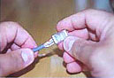
1. Skin off the cable jacket approximately 1" or slightly more.
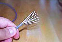
2. Un-twist each pair and straighten each wire between the fingers.
3. Place the wires in the order of one of the two diagrams shown above (568B or 568A). Bring all of the wires together, until they touch.
4. At this point, recheck the wiring sequence with the diagram.
5. Optional: make a mark on the wires at 1/2" from the end of the cable jacket.
6. Hold the grouped (and sorted) wires together tightly, between the thumb, and the forefinger.
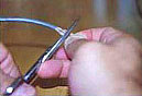
7. Cut all of the wires at a perfect 90 degree angle from the cable at 1/2" from the end of the cable jacket. This is a very critical step. If the wires are not cut straight, they may not all make contact. I suggest using a pair of scissors for this purpose.
7B. Conductors should be at a straight 90 degree angle, and be 1/2" long, prior to insertion into the connector.
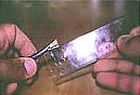
8. Insert the wires into the connector (pins facing up).
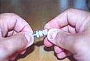
9. Push moderately hard to assure that all of the wires have reached the end of the connector. Be sure that the cable jacket goes into the back of the connector by about 3/16".
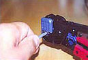
10. Place the connector into a crimp tool, and squeeze hard so that the handle reaches it's full swing.
11. Repeat the process on the other end. For a straight through cable, use the same wiring.
For a "crossover" cable, wire one end 568A, and the other end 568B.
12. Use a cable tester to test for proper continuity.
Notes Regarding Making Category 5 Patch Cable
- The RJ-45 plugs are normally made for either solid conductors or stranded conductors. It is very important to be sure that the plug that you use matches the conductor type. It is extremely difficult to tell the difference between the two by looking at them. When you buy these plugs, be sure to categorize, and store them carefully. Using the wrong type can cause intermittent problems. The RJ-45, 8 Conductor Plugs that we sell are rated for both Solid and Stranded cable.
- Ordinarily, it would be taboo to untwist the pairs of any category 5e cable. The one exception to this rule is when crimping on RJ-45 plugs. It would be impossible to insert the wires into the channels without first untwisting and straightening them. Be sure not to extend the un-twisting, past the skin point. If you do it properly, you will wind up with no more than 1/2" of untwisted conductors (up to 1/2" of untwist meets the cat 5 specification).
- If the completed assembly does not pass continuity, you may have a problem in one, or both ends. First try giving each end another crimp. If that does not work, then carefully examine each end. Are the wires in the proper order? Do all of the wires fully extend to the end of the connector? Are all of the pins pushed down fully. Cut off the suspected bad connector, and re-terminate it. If you still have a problem, then repeat the process, this time giving more scrutiny to the end that was not replaced.
- It is good to be prepared to make your own patch cables. There may be many instances where you may fall short on supply, and making a cable will surely get you out of a jam. However, there comes a point where the practicality curve will lead you to factory made cables. Making several cables can be very labor intense. Factory made cables typically have better tolerances, and consequently have better quality than field made cables.
Controversies and Caveats: Category 5, 5E, and Cat 6 Patch Cables
568B vs. 568A
For patch cables, 568-B wiring is by far, the most common wiring method. Virtually all pre-assembled patch cables are wired to the B standard. There is no difference in connectivity between 568B and 568A cables. Therefore, a 568B patch cable should work fine on a 568A cabling system, and visa-versa. To my knowledge, there has never been an issue with networks of up to 100 megabits. However, with the advent of Gigabit over copper cabling, it may very well become a factor at some point. I have conferred with several cable manufacturers, and many other technical resources, on this subject. The consensus is that mixing of the standards on patch cables should not cause a problem. Since Gigabit networks over copper cabling are in their infancy, and no one can say for sure, I would advise you to take the safe approach on all future patch cable implementations.
Re-use of old cables
I have seen this happen time and time again. Perfectly good patch cables that have been working fine for years, get removed from their installation, and re-installed on the same, or different network. The result can be a nightmare. What happens is that the cable, over time, adapts to the way that it is bent in it's original installation. When these cables are removed and re-installed, they can either completely loose their connection, or develop intermittent problems. This is due to stresses that may be opposite to what they were originally subject to. If the integrity of your network is more valuable than the price of new patch cables, then I strongly suggest that you use brand new cables for all closet cleanups, network moves, etc.
Stranded vs. Solid wire
Almost all patch cables that are made have stranded wire. Stranded wire is normally specified for use in patch cables due to it's superior flexibility. There has been some talk recently, in the technical sector of the structured wiring community, regarding the possible use of solid conductors for patch cables. The reason for the spotlight on solid wire is that it is supposedly more stable, under a variety of conditions.