Overview
The Network layer protocols are responsible for the establishment, maintenance, and termination of end-to-end links. Network layer protocols are required when end devices (or hosts) that are not physically connected to the same LAN must communicate.
Network layer protocols are part of a particular network operating system's protocol stack. Different network operating systems may use different Network layer protocols. Many network operating systems have the ability to use more than one Network layer protocol. This capability is especially important to heterogeneous, multi-platform, multi-vendor client/server computing environments.
Most Network layer protocols are part of a suite of protocols. In the case of the TCP/IP protocol suite, the Internet Protocol (IP) resides at the Network layer while the Transmission Control Protocol (TCP) operates at the Transport layer. The TCP/IP protocol suite also consists of numerous other protocols including protocols that operate at the Application layer including, but not limited to: the HyperText Transfer Protocol (HTTP), the File Transfer Protocol (FTP), and the Simple Mail Trasfer protocol (SMTP). TCP/IP also consists of other protocols which operate at the Network layer as well like: the Internet Control Messaging Protocol (ICMP), the Address Resolution Protocol (ARP), and the Internet Group Multicating Protocol (IGMP). All of these protocols work in concert with each other to coordinate and package network communications between devices.
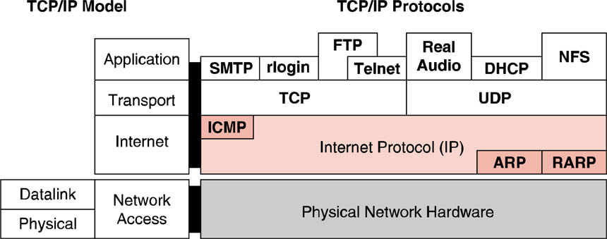 Depiction of the components of the Internetwork/Network layer in the TCP/IP protocol stack.
Other notable Network layer protocols include: Novell's Sequenced Packet Excahnge (SPX) protocol, which is part of the Novell IPX/SPX suite of networking protocols; and Apple's Datagram Delivery Protocol (DDP) found in its AppleTalk suite of network protocols.
Network layer protocols are primarily responsible for providing an end-to-end logical addressing scheme and the routing of packets based on that addressing scheme. Routing of packets refers to determining if a packet's destination is local (same network as sender) or remote (different network from sender) and handling the forwarding of the packet accordingly.
Addressing
Single network segments are commonly referred to as
segments, subnetworks, or subnets. Inter-connected segments are referred to as
networks, internetworks, or intranets.
The Network layer provides end-to-end or inter-segment communications. The host address must be unique within a network segment. Network layer packets are routed to the network segment of the correct host based on the segment address.
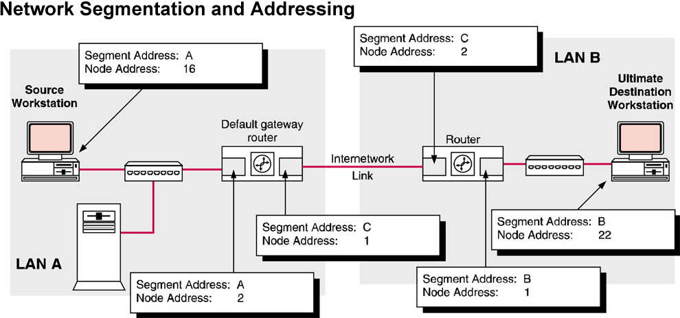 Depiction of how a network layer device, like a router, provides for network segmentation and addressing.
The Network layer must provide a mechanism for addressing these end devices. If individual pieces of data are to be directed to an end device, that device must have a unique address. In an IPv4 network, when this address is added to a device, the device is then referred to as a host.
Address Resolution
The Data Link layer uses the physical address (also known as the MAC address) of the NIC to deliver data rather than the network layer host address. For the Network and Datalink layers to successfully interact to deliver data, a direct, one-to-one mapping must be made between the Network layer address and the Datalink layer physical address.
The process of resolving the Data Link layer address of a host NIC to its Network layer address is known as address resolution. Each NIC is assigned a single Data Link layer address and one or more (multi-homed) Network layer address(es).
The Address Resolution Protocol (ARP)
The protocol used at the Network layer for resolving and managing address resolution is the Address Resolution Protocol (ARP). Before a host device can send a message across the network to another device, it must first resolve the destination host's Network layer address to its Data Link layer address. In order to do this, the sending device will create an ARP Request packet and broadcast it onto the network segment the sending host is physically attached to. Since the destination address of the ARP packet is a Data Link layer broadcast address (an all 1s destination address), all hosts on that segment will accept receipt of the message and hand it up to its Network layer where the message's Network layer destination address is compared to each host device's Network layer address(es).
If the two Network layer addresses do not match then the device simply discards the message. However, if the message's Network layer destination address does match one of the host device's Network layer addresses, then the host device will respond with an ARP Response packet sent back to the host which originated the ARP Request. In the ARP Response packet, the responding device includes the matching Network layer address and its corrsponding Data Link layer (MAC) address. The device that originated the ARP request receives the ARP response and stores both the destination device's Network layer address and its corresponding Data Link layer address in its own ARP Table (see example ARP table) and uses the information to insert the Data Link layer address into any messages intended for that destination device.
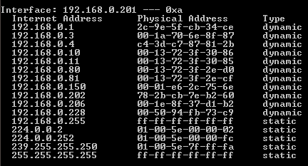
Example ARP table.
As long as a sending device has a mapped Network layer/Data Link layer entry in its ARP table, the device will use that entry in the ARP table when addressing future messages to the same device without having to re-initiate the ARP Request/ARP Response process. Entries in the ARP table are removed after two minutes, unless the entry is reused. If they are reused within the initial two minute time frame the time-to-live for that entry will increase to ten minutes.
Notice in the ARP table that are are two types of ARP entries, dynamic and static. Dynamic entries are created by the request/response process describe above and static entires are created by the device's operating system during initialization of the device or when an entry is specified to be static by the device's administrator.
Encapsulation
The Network layer must also provide encapsulation. Not only must the devices be identified with an address, the individual pieces - the Network layer PDUs - must also contain these addresses. During the encapsulation process, Layer 3 receives the Layer 4 PDU and adds a Layer 3 header, or label, to create the Layer 3 PDU. When referring to the Network layer, we call this PDU a packet. When a packet is created, the header must contain, among other information, the address of the host to which it is being sent. This address is referred to as the destination address. The Layer 3 header also contains the address of the originating host. This address is called the source address.
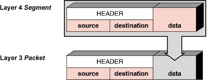
After the Network layer completes its encapsulation process, the packet is sent down to and encapsulated by the Data Link layer to be prepared for transportation over the media.
Routing
The Network layer must provide services to direct these packets to their destination host. The source and destination hosts are not always connected to the same network. In fact, the packet might have to travel through many different networks. Along the way, each packet must be guided through the network to reach its final destination. Intermediary devices that connect the networks are called routers. The role of the router is to select paths for and direct packets toward their destination. This process is known as routing.
During the routing through an internetwork, the packet may traverse many intermediary devices. Each route that a packet takes to reach the next device is called a hop. As the packet is forwarded, its contents (the Transport layer PDU), remain intact until the destination host is reached.
Decapsulation
When a packet arrives at its destination host and is processed at the Network layer. The host examines the destination Network layer address to verify that the packet was addressed to this device. If the address is correct, the packet is decapsulated by the Network layer and the Transport layer PDU contained in the packet is passed up to the appropriate service at Transport layer.
Unlike the Transport layer (OSI Layer 4), which manages the data transport between the processes running on each end host, Network layer protocols specify the packet structure and processing used to carry the data from one host to another host. Operating without regard to the application data carried in each packet allows the Network layer to carry packets for multiple types of communications between multiple hosts.
Internet Protocol Version 4 (IPv4)
The Network layer services implemented by the TCP/IP protocol suite are the Internet Protocol (IP). Version 4 of IP (IPv4) is currently the most widely-used version of IP. It is the only Layer 3 protocol that is used to carry user data over the Internet and is the focus of the CCNA. Therefore, it will be the example we use for Network layer protocols in this course.
IP version 6 (IPv6) is developed and being implemented in some areas. IPv6 will operate alongside IPv4 and may replace it in the future. The services provided by IP, as well as the packet header structure and contents, are specified by either IPv4 protocol or IPv6 protocol. These services and packet structure are used to encapsulate UDP datagrams or TCP segments for their trip across an internetwork.
The characteristics of each protocol are different. Understanding these characteristics will allow you to understand the operation of the services described by this protocol.
The Internet Protocol was designed as a protocol with low overhead. It provides only the functions that are necessary to deliver a packet from a source to a destination over an interconnected system of networks. The protocol was not designed to track and manage the flow of packets. These functions are performed by other protocols in other layers.
IPv4 basic characteristics
- Connectionless - No connection is established before sending data packets.
- Best Effort (unreliable) - No overhead is used to guarantee packet delivery.
- Media Independent - Operates independently of the medium carrying the data.
The Internet Protocol (IP) is defined in RFC 791 http://www.ietf.org/rfc/rfc0791.txt
As shown in figure, an IPv4 protocol defines many different fields in the packet header. These fields contain binary values that the IPv4 services reference as they forward packets across the network.
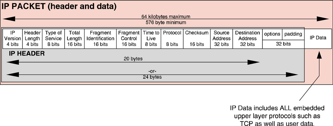
This course will consider these 6 key fields:
- IP Destination Address
- IP Source Address
- Time-to-Live (TTL)
- Protocol
- Type-of-Service (ToS)
- Fragment Offset
IP Destination Address
The IP Destination Address field contains a 32-bit binary value that represents the packet destination's Network layer host address.
IP Source Address
The IP Source Address field contains a 32-bit binary value that represents the packet source's Network layer host address.
Time-to-Live
The Time-to-Live (TTL) is an 8-bit binary value that indicates the remaining "life" of the packet. The TTL value is decreased by at least one each time the packet is processed by a router (that is, each hop). When the value becomes zero, the router discards or drops the packet and it is removed from the network data flow. This mechanism prevents packets that cannot reach their destination from being forwarded indefinitely between routers in a routing loop. If routing loops were permitted to continue, the network would become congested with data packets that will never reach their destination. Decrementing the TTL value at each hop ensures that it eventually becomes zero and that the packet with the expired TTL field will be dropped.
Protocol
This 8-bit binary value indicates the data payload type that the packet is carrying. The Protocol field enables the Network layer to pass the data to the appropriate upper-layer protocol.
Example values are:
For a complete list of values for used in the IP Protocol Number
field: http://www.iana.org/assignments/protocol-numbers
Type-of-Service
The Type-of-Service field contains an 8-bit binary value that is used to determine the priority of each packet. This value enables a Quality-of-Service (QoS) mechanism to be applied to high priority packets, such as those carrying telephony voice data. The router processing the packets can be configured to decide which packet it is to forward first based on the Type-of-Service value.
Fragment Offset
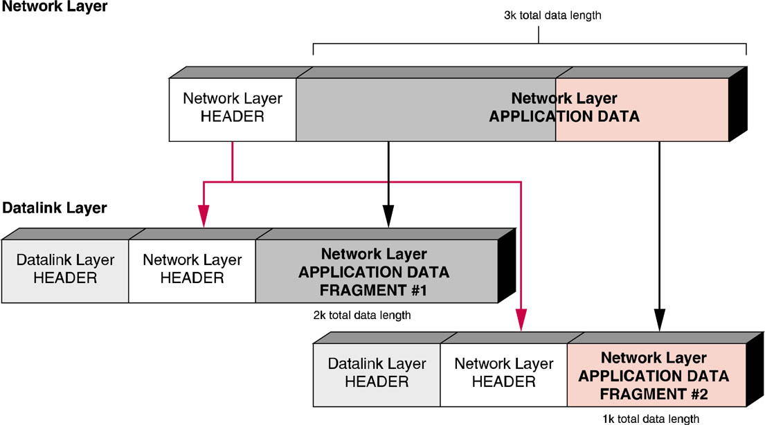
As mentioned earlier, a router may have to fragment a packet when forwarding it from one medium to another medium that has a smaller MTU. When fragmentation occurs, the IPv4 packet uses the Fragment Offset field and the MF flag in the IP header to reconstruct the packet when it arrives at the destination host. The fragment offset field identifies the order in which to place the packet fragment in the reconstruction.
More Fragments Flag
The More Fragments (MF) flag is a single bit in the Flag field used with the Fragment Offset for the fragmentation and reconstruction of packets. The More Fragments flag bit is set, it means that it is not the last fragment of a packet. When a receiving host sees a packet arrive with the MF = 1, it examines the Fragment Offset to see where this fragment is to be placed in the reconstructed packet. When a receiving host receives a frame with the MF = 0 and a non-zero value in the Fragment offset, it places that fragment as the last part of the reconstructed packet. An unfragmented packet has all zero fragmentation information (MF = 0, fragment offset =0).
Don't Fragment Flag
The Don't Fragment (DF) flag is a single bit in the Flag field that indicates that fragmentation of the packet is not allowed. If the Don't Fragment flag bit is set, then fragmentation of this packet is NOT permitted. If a router needs to fragment a packet to allow it to be passed downward to the Data Link layer but the DF bit is set to 1, then the router will discard this packet.
Internet Control Messaging Protocol (ICMP) Packet

Packet Internet Groper (PING)
The Packet Internet Groper is a utility which is part of the TCP/IP protocol suite. PING uses ICMP packets to do its work. It is commonly used as a testing tool to determine if the Network layer of the data communication device is operating correctly. This is done by first attempting to "ping" the device's network interface by using its loopback address of 127.0.0.1; then to test if the device's network interface can communicate with the Network layer of other devices on the local area network or remotely you can use the IP address of the device you want to communicate with. PING www.microsoft.com, for example.
Below is the PING help screen. To view this information in a command window type "PING /?".
    Usage: ping [-t] [-a] [-n count] [-l size] [-f] [-i TTL] [-v TOS]
                [-r count] [-s count] [[-j host-list] | [-k host-list]]
                [-w timeout] target_name

    Options:
        -t             Ping the specified host until stopped.
                       To see statistics and continue - type Control-Break;
                       To stop - type Control-C.
        -a             Resolve addresses to hostnames.
        -n count       Number of echo requests to send.
        -l size        Send buffer size.
        -f             Set Don't Fragment flag in packet.
        -i TTL         Time To Live.
        -v TOS         Type Of Service.
        -r count       Record route for count hops.
        -s count       Timestamp for count hops.
        -j host-list   Loose source route along host-list.
        -k host-list   Strict source route along host-list.
        -w timeout     Timeout in milliseconds to wait for each reply.