Overview
The second layer of the OSI Network Reference Model is the
Data Link layer. The Data Link layer provides point-to-point connectivity between network nodes over the physical connections provided by the underlying Physical layer. In order for two devices to communicate at the
Data Link layer there must be some sort of physical channel in place between them; data sent from the
Data Link layer of one device must be automatically delivered to the Data Link layer of the destination device by the Physical layer. The manner in which this communication takes place can be over a physical circuit (as in a modem to modem connection) or a logical circuit (as in a shared media local area network such as Ethernet). The
Data Link layer is of particular interest to the study of local area networks as this is the layer in which network architectures are defined. The
standards are debated and established by the Institute of Electrical and Electronic Engineers (IEEE) 802 committee. The 802 designation is derived from the date when the
committee was first formed, in 1980 (80) in the month of February (2).
Frames and Cells
The Data Link layer breaks a data stream into chunks called frames or cells, depending on the technology used, and then transmits them to the destination device. In the case of an Ethernet network they are called frames. In Asynchronous Transfer Mode (ATM) networks they are called cells. These frames of data have a header that contains a start delimiter and information about the frame followed by the data itself, followed by a Frame Check Sequence (FCS) and then some sort of stop delimiter to note the end of the frame.
Data Link layer frames are built within the Network Interface Card (NIC) installed in a computer according to a predetermined frame layout particular to the network architecture of the installed network interface card.
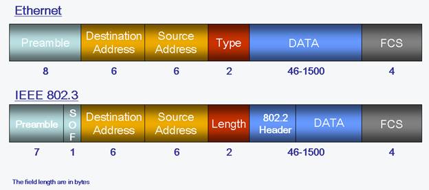
 Detailed depiction of Ethernet and IEEE 802.3 frame fields.
Data Link layer protocols govern how to format a frame or cell for use on different media. At each hop along the path, an intermediary device accepts the frame or cell from one medium, decapsulates the frame, then forwards the packets in a new frame. The headers of each frame are
formatted for the specific medium that it will cross.
Data Link Sublayers
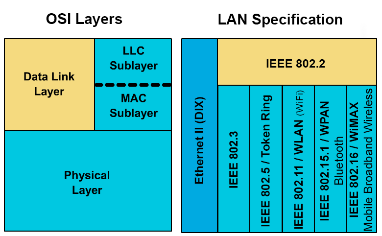
In local area networks, the Data Link layer can be broken down into two sublayers: Media Access Control (MAC) and Logical Link Control (LLC). In the original
Ethernet frame format there was no LLC used, instead a type field was used to indicate which API should be used to process the frames contents at Layer three. In an IEEE 802.3 frame an 802.2 (LLC) header is added to identify the layer three protocol used to process the data contained within the frame. The MAC sublayer of the
Data Link layer is used to add and process the source and destination address in the frame. A MAC address is also referred to as the Physical address or Logical address. The MAC address of the network interface is burned into the device by its manufacturer.
 Depiction of the OSI model physical layer and datalink sublayers and how they map to LAN specifications.
Access Control
The Data Link layer also controls how data is placed onto the media using an access control method like Carrier Sensing Multiple Access/Collision Detection (CSMA/CD), Carrier Sensing Multiple Access/Collision Avoidance (CSMA/CA), or token passing. Ethernet networks use CSMA/CD, Apple's
Local Talk networks use CSMA/CA, and Token Ring networks use token passing. When data
communication devices need to communicate over a shared media it is important to try and avoid collisions. That is to say no two devices should be transmitting on the shared media at the same time, otherwise their transmissions will collide and corrupt each other's transmission, rendering them both useless. By using an access control method data communication devices are less likely to try and transmit messages onto the shared media when there is already a message being transmitted on the shared media. By using Carrier Sensing the data communication device attempts to detect whether or not their is already a message on the media before attempting to transmit its own message.
In the rare occasion where carrier sensing is not successful, Collision Detection alerts the transmitting devices that their messages have collided and thereby become unusable. The transmitting devices then set a timer, each using a different randomly selected number of milliseconds and wait until their timer expires before attempting to re-transmit its previous message. In the case of Collision Avoidance, a small message is transmitted first before the actual message is transmitted. If no collision occurs, the device then transmits its message. With token passing a small message called a token is constantly travelling the network from device to device. Only when a device
possesses the token can it transmit a message. Studies have shown that CSMA/CD is more efficient than the other access control methods and more scalable to larger networks as well.
Error Detection
Another important function of the Data Link layer is error detection. Error detection is accomplished by using a Frame Check Sequence (FCS) method like Parity, Checksum Calculation or Cyclic Redundancy Check (CRC).
Parity
Parity, is also know as a Vertical Redundancy Check (VRC) and is the simplest error detection method. Parity works by adding an error check bit to each character. For example, since the ASCII 7-bit code for the letter A is 1000001, a parity bit is added the
eighth bit. Whether this bit should be a 0 or a 1 depends on whether odd or even parity is being used. Using no parity is also an option. Examples of the letter A with odd and even parity are illustrated in the figure below.
 Depiction of how odd and even parity is implemented in vertical redundancy checks (VRCs)
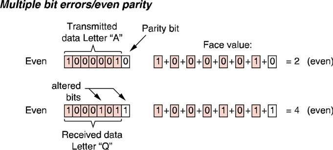
The problem with parity is that it can only detect odd numbers of bit substitution errors, i.e. 1 bit, 3bit, 5, bit, etc. errors. If there two, four, six, etc. bits which are transmitted in error, using VRC will not be able to detect the error. This problem is demonstrated in the figure below.
 Illustration of the problem with variable redundancay checks when more than one bit is in error.
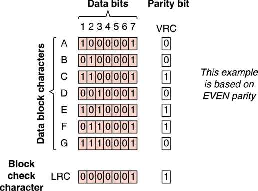
Longitudinal Redundancy Checks (LRC) seek to overcome the weakness of simple, bit-oriented, one-directional parity checking. Think of LRC as adding a second dimension to parity checking. As you can see in the figure below, LRC is block-oriented parity checking which adds the VRC parity values from a block of characters and arrives at a second parity value by which to check the data with. Upon receipt, each character is checked according to its VRC parity value and then the entire block of characters is verified using the LRC block check character.
 Illustration of how longitudinal redundancy checks overcomes the weakness of simple, bit-oriented, one-directional parity checking.
Checksum Calculations
A Checksum calculation is performed the device adding the ASCII decimal value of each of the 128 characters in a block, dividing the sum by 255, and determining the remainder. The remainder is the checksum character which is transmitted in the FCS field and verified by the receiving device which performs the same checksum calculation and determines if its remainder matches the decimal value of the character stored in the FCS.
If you are not familiar with ASCII values, a quick review of the ASCII table will help you to better understand how a checksum calculation works.
| Power of 2 |
7 |
6 |
5 |
4 |
3 |
2 |
1 |
0 |
|
| Decimal Value |
128 |
64 |
32 |
16 |
8 |
4 |
2 |
1 |
|
| Letter "A" Code |
0 |
1 |
0 |
0 |
0 |
0 |
0 |
1 |
= 65 |
Example of how the ASCII table defines the character encoding value for the letter "A"
As demonstrated in the table above the decimal value of the capital letter "A" is 65. If 128 capital A's were transferred in a single block of data, the total value of the block would be 128 X 65 = 8,320. Now divide that total by 255, 8,320/255 = 32 with a remainder of 160. The remainder is also known as the least significant byte. In order to represent the remainder of 160 as a single checksum character, it must be converted to binary which would result in 10100000.
Cyclic Redundancy Check
Cyclic Redundancy Checks (CRC) seek to improve on the error detection capability of checksums and LRCs. A CRC is really a more sophisticated form of a checksum. In order to understand CRCs, binary division is required. In cyclic redundancy checking the entire message block of ones and zeroes, even if it's 1,000 bits long, is treated as a single gigantic binary number. This
gigantic string of ones and zeroes is divided by a predetermined prime binary number one bit longer than the desired number of bits in the CRC value. Remembering that if these divisors are prime (only divisible by one themselves) they will produce a remainder one bit shorter than themselves. Common lengths for CRCs are 16 and 32 bits. A 16-bit CRC uses a 17-bit divisor and a 32-bit CRC uses a 33-bit divisor.
This remainder is then attached to the actual data message (the original string of ones and zeroes) and transmitted to the receiving device where the received data string is again divided by the same divisor. The remainder calculated at the receiving device is compared to the remainder received from the transmitting device.
Using this technique, an error burst up to one bit less than the CRC (15 bits for a 16-bit CRC and 31 bits for a 32-bit CRC) can be detected 100 percent of the time, and larger error bursts at 100-1/2(number of bits in the CRC percent of the time. Using this formula to compute the overall percentage for a 16-bit CRC yields an error detection rate of 99.999984742 percent.